The code below inserts the flash interface into your SoCs.
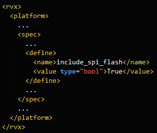
An example is provided in #(example dir)/test_flash.xml.
v2025-07-10 or later
This tutorial introduces a method for building standalone FPGA prototypes using flash memory.
By storing the FPGA bitstream and application in flash memory, the application automatically starts when power is supplied.
Not all FPGA boards are supported.
An FPGA board connected to your computer - Manual
Any part starting with # should be replaced or modified according to your environment.
On Linux, use the bash shell for command-line operations.
On Windows, use the Windows Power Shell for command-line operations.
#(cloned directory)/rvx_platform_example/test_flash
This directory will hereafter be referred to as #(example dir).
The code below inserts the flash interface into your SoCs.
An example is provided in #(example dir)/test_flash.xml.
cmd) cd #(example dir)
cmd) make syn
cmd) make arty-100t // or the FPGA board you have
cmd) cd imp_arty-100t_XXXX // referred to as #(fpga dir)
cmd) make impcmd) cd #(fpga dir)
inst) Connect the FPGA board to your computer.
cmd) make program_flash
inst) Turn the power of the FPGA board off and on.
cmd) make printf
cmd) make hello.all
inst) Check whether the application is working properly.cmd) cd #(fpga dir)
cmd) make flash_server
cmd) make printf
cmd) make hello.flash BUILD_MODE=release
inst) Set the boot mode switch to ON.
inst) Press the reset button on the FPGA board.
inst) Check whether the application is working properly.inst) Set the boot mode switch to ON.
inst) Turn the power of the FPGA board off and on.
inst) Check whether the application is working properly.Assume that you have a fully developed platform.
Write the code for the flash interface in your #(platform xml).
Copy ‘flash_server’ from #(example dir)/app to #(platform dir)/app
Run the commands you learned from this tutorial.
Make sure to set the boot mode switch to OFF.